

XMEGA tutorial: LCD display (05)
atxmega
,
lcd display
,
lcd driver
,
tutorial
,
xmega
|
Blinking diodes mentioned in the previous part of our tutorial is cool, however not very communicative. That's why before moving on to discussing particular peripherals of XMEGA microcontrollers, we will learn how to operate 16x2 LCD text display with HD44780 driver.
This paragraph’s aim is to acquaint the reader with basic knowledge on how to control the display, although we are not going to create it’s function library from scratch. Instead, we will use a template provided by Radosław Kwiecień and available on his website radzio.dxp.pl. I have adjusted his function library to work with XMEGA microcontrollers, so that we can use the display in following parts of the preparation course. We will see how new libraries can be added to the Atmel Studio project by the way.
This paragraph’s aim is to acquaint the reader with basic knowledge on how to control the display, although we are not going to create it’s function library from scratch. Instead, we will use a template provided by Radosław Kwiecień and available on his website radzio.dxp.pl. I have adjusted his function library to work with XMEGA microcontrollers, so that we can use the display in following parts of the preparation course. We will see how new libraries can be added to the Atmel Studio project by the way.
XMEGA tutorial: ports (04)
Port is the fundamental peripheral, which enables connection between microcontroller and other devices. In well known and appreciated processors: ATtiny & ATmega each port used to have three registers: PIN, PORT and DDR. However in XMEGA microcontrollers there are 21 registers for each port... but don't worry! Using the XMEGA ports is even easier than in ATmega!
All ports have unique name: PORTA, PORTB, PORTC... and so on until the end of alphabet! Within each port there are several registers and some of the most important are listed below:
All ports have unique name: PORTA, PORTB, PORTC... and so on until the end of alphabet! Within each port there are several registers and some of the most important are listed below:
- DIR – this one register decides which of the pins is supposed to be an input or output. Typing 1 will configure the pin as an output and 0 as input. For example, the instruction below sets pins 3 and 6 as outputs, therefore the other pins will be inputs:
PORTA.DIR = PIN3_bm | PIN6_bm;
- OUT - this is the output register. Typing 1 will cause the appearance of high state of appropriate "leg" of port, while 0 means low state.
- IN – is the input register, used for reading current pin state. Here is the example of conditional statement (branch control structure) which checks if the state on the pin E5 is high:
if(PORTE.IN & PIN5_bm)
XMEGA tutorial: new methods of registers configuration (03)
atxmega
,
course
,
register configuration
,
tutorial
,
xmega
|

XMEGA tutorial: first program (02)
atxmega
,
course
,
first program
,
tutorial
,
xmega
|
You will be introduced to Atmel Studio and you’ll find out how to download programs to X3-DIL64 from Leon Instruments.
Download:
XMEGA tutorial: what you should know (01)

Discover XMEGA
atxmega
,
breakout
,
development board
|
Don't stay behind! Discover new XMEGA from Atmel!
Let us introduce you to the new ATxmega128A3U development board from Leon Instruments. It is populated with every basic peripheral you need to get started with new XMEGA.

With a X3-DIL64 prototyping module you are free to connect any device with ease and convenience. Plug it into the breadboard, just like any integrated circuit, program it and go! It’s so easy. The board’s dimensions are suited to fit conventional DIL64 packages, and pin order is exactly the same as in a processor’s TQFP64 package. That’s why you can apply this module to your EDA software without creating a new library.

ATxmega128A3U microprocessor can be programmed three ways:


Don’t like the crystal oscillator hard-soldered to the board without any possibility to change processors clock frequency? Sure! We hate it too! That’s why X3-DIL64 module provides a socket for any oscillator of your choice – just plug it into the socket.

The X3-DIL64 prototyping module is populated with a microSD socket to have as much memory as your application requires. The microSD card is connected to the processor via SPI interface. Although you don’t need external memory, there’s a possibility to use SPI pins for any other purpose, because they are available on the edge connectors, similar to other microcontroller’s pins


Links:Atmel accomplished a quantum leap introducing new XMEGA microcontrollers. They are much faster, have more peripherals and their price is reasonable. Some of them are even lower cost than traditional ATmega. Don’t wait any longer. Step ahead to explore these fantastic units and use them to design much better devices.
ATxmega128A3U in DIL64
Let us introduce you to the new ATxmega128A3U development board from Leon Instruments. It is populated with every basic peripheral you need to get started with new XMEGA.

ATxmega128A3U peripherials:
|
 |
DIL64 package
With a X3-DIL64 prototyping module you are free to connect any device with ease and convenience. Plug it into the breadboard, just like any integrated circuit, program it and go! It’s so easy. The board’s dimensions are suited to fit conventional DIL64 packages, and pin order is exactly the same as in a processor’s TQFP64 package. That’s why you can apply this module to your EDA software without creating a new library.

Programming
ATxmega128A3U microprocessor can be programmed three ways:
- PDI interface - it allows you to download/upload the memory and configure the device setting
- FLIP bootloader - innovative Atmel’s solution for people who don’t own PDI nor JTAG programmer. Just plug in the usual USB cable and go! It’s the best solution for beginners
- JTAG interface - although the JTAG connector isn’t present on the board, it’s possible to program and debug the device with the JTAG programmer


Free to select the crystal
Don’t like the crystal oscillator hard-soldered to the board without any possibility to change processors clock frequency? Sure! We hate it too! That’s why X3-DIL64 module provides a socket for any oscillator of your choice – just plug it into the socket.

Memory will never run out
The X3-DIL64 prototyping module is populated with a microSD socket to have as much memory as your application requires. The microSD card is connected to the processor via SPI interface. Although you don’t need external memory, there’s a possibility to use SPI pins for any other purpose, because they are available on the edge connectors, similar to other microcontroller’s pins

Power supply
And again, with X3-DIL64 you are free to select the power source:- From USB – you can power the module directly from your computer
- From your programmer – if your PDI programmer supports powering the programmed device, with X3-DIL64 this is also possible
- From any 5V or 3.3V source – simply, provide power from anything you want!


Welcome to the Leon Instruments!
|
Welcome to the Leon Instruments! You will find here many interesting projects of devices that you can build yourself. Also, you'll get the detailed description of the electronic design.
This site is currently being translated to English. I started translating in 2014 and I keep translating... please be patient!
This site is currently being translated to English. I started translating in 2014 and I keep translating... please be patient!
Recently added
 |
Gallery: Integrated circuits Watching these ancient integrated circuits you can realize how fastly the world is changing. Most of them come from 1970s or 1980s. It's not too long period of time, just 30 years! But they are completely different than ICs used nowadays. |
 |
Gallery: old chips In old IC's transistors were so large that you can see them even without a microscope. Thank's to this, pictures are very clear and having some knowledge about IC manufacturing you can work out where are some gates, flip-flops and others! |
 |
Intel Confidential Processor Prototypes These artifacts do not belong to my collection, because I would have to spend almost $10,000 for them! They are amazing integrated circuits. In general, manufacturers destroy all the prototypes when no longer needed. But somehow some prototypes survived. |
 | |
Gallery: Intel Confidential Processor Prototypes
chip
,
integrated
,
Intel Confidential
,
processor
,
prototype
|
LinksThese artifacts do not belong to my collection, because I would have to spend almost $10,000 for them - the seller on e-bay wishes to $1,000 for each unit! Although it must be admitted that they are amazing integrated circuits. In general, manufacturers destroy all the prototypes when no longer needed. But somehow some prototypes survived.
Boards you can see here are prototype processor systems, mounted on a very strange test boards. It is difficult to say exactly how it was used and why it is mounted on such boards, and not in the target housing. Little golden round pads are testpoints, which can be connected with a spring wire pins. However, what does the rest of the components you see in the pictures ... I have no idea.

Intel Confidential CPU Development CF64BJF006


Intel Confidential CPU Development CF64BJF010


Intel Confidential CPU Development CF64BJF012


Intel Confidential CPU Development TY56ANF012


Intel Confidential CPU Development WM56ARF400


Intel Confidential CPU Development WM56ARF405


Intel Confidential CPU Development YNHMRM-GX


Intel Confidential CPU Development BGCRF0A086


MicroProbe INTEL CUSTOM R60 S25D REV.B
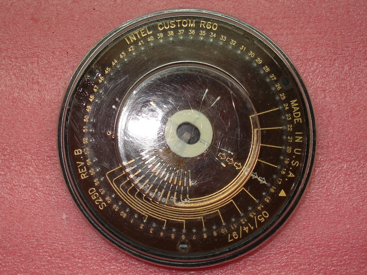
MicroProbe INTEL CUSTOM R60 SP46A REV.B

MicroProbe PCIN 40MP INTEL CUSTOM R60 S20AA REV.A

Intel Confidential Pentium P55C


Links
Subscribe to:
Posts
(
Atom
)


